

Microseismic monitoring
Microseismic monitoring provides a 4D measurement of the induced microseismic ‘events’ associated with hydraulic fracturing. The hypocenter of the events are obtained using a downhole or surface array of three component geophones. Microseismic projects are complex requiring the coordination of several well site operations and the consideration of many factors from equipment selection to well preparation and HSE. Clearly designed project objectives and success criteria are required.

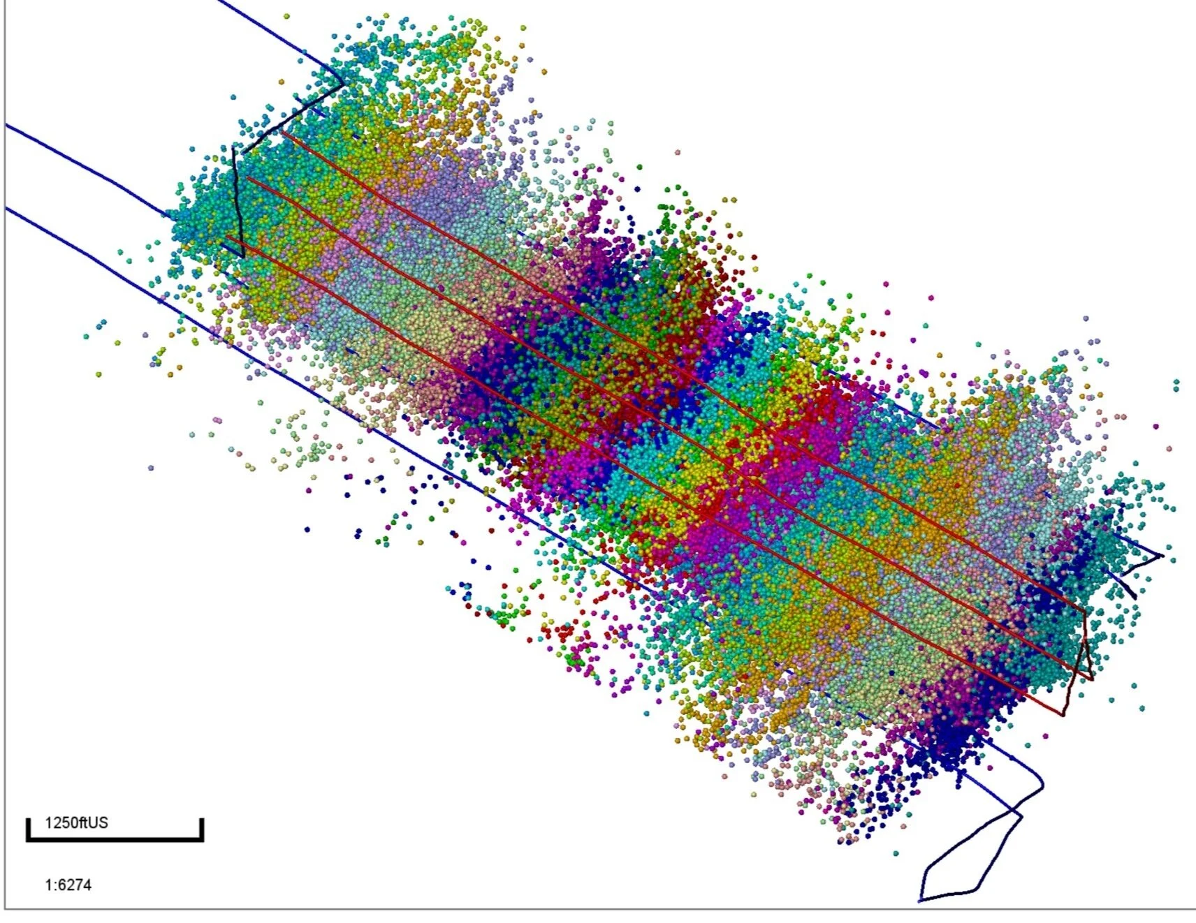
MSEEL MIP 5H Microseismic ESVs plan view

MSEEL MIP 5H Microseismic ESVs depth view

MSEEL MIP 5H Microseismic 3D view
Microseismic project planning & design
Thorough project planning and design is essential and begins with an assessment of the available well geometry (monitor wells and treatment wells), the planned completion schedule and any previous monitoring projects completed locally. There are many potential survey designs for a microseismic project, each has advantages and disadvantages. Selection is based on an understanding of well geometry, cost and project objectives. In most cases operators need to work with the monitor wells available.

Static vertical array
This is the simplest deployment and most cost effective if project objectives can be achieved. The array is lowered under gravity and remains in one position throughout the survey. All events are recorded from the same array location resulting in a significant distance bias in the data.

Tractored array
The introduction of a tractor adds cost and complexity. Event location are now heavily dependent on the horizontal axis of the receiver array. The advantage of this deployment is the ability to maintain proximity to the active stage of the completion thus reducing distance bias in the data and likely recording more lower magnitude events.

Split array
The split array has two sub arrays connected with wireline and deployed by a tractor. Array weight will limit the extent the array can be tractored and each sub array is shorter than an independent vertical or horizontal array. The advantage is the array can detect events on either sub array and potentially both.

Multi well arrays
Assuming appropriate geometry, utilizing multiple monitor wells will improve the sensitivity of the overall receiver network and result in less distance bias and more lower magnitude events recorded.
Pre survey modeling is a requirement for all microseismic projects and likely several iterations; at the project inception phase, once the initial velocity model is built and once the receiver array is deployed immediately prior to the commencement of acquisition. Utilizing the velocity model and receiver array, and based on assumptions on background noise and the subsequent impact on timing and Hodogram errors, an estimate of likely minimum event magnitudes and their associated location errors can be made. Synthetic events can also be generated. It is good practice (but rarely done) to assess the validity of these pre job assumptions using the measured data post job.

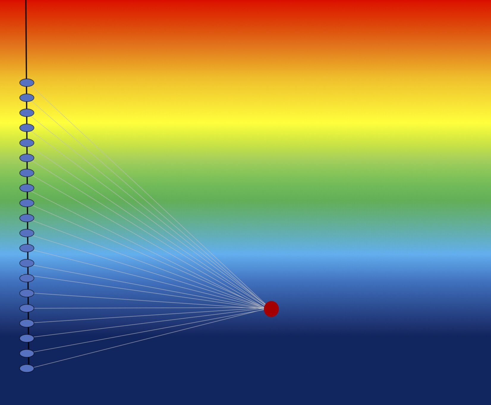
“An example of synthetic waveform modeling for a double-couple source mechanism. An array consisting of 43 receivers is used in a vertical well to record waveform data. P- and S-nodal axes are indicated with blue and red arrows on the wavefront propagation plot.”
Akram et al, CSEG Recorder, 2016, vol 41, no. 02. ‘An Overview of Microseismic Acquisition Project Management’.

“An example of event detectability modeling. Actual microseismic events recorded in the field experiment (Eaton et al., 2014) are also shown which agree in general with the modeling results. The maximum and minimum P-wave velocities in the model are 4520m/s and 2306 m/s, respectively.”
Akram et al, CSEG Recorder, 2016, vol 41, no. 02. ‘An Overview of Microseismic Acquisition Project Management’.

Microseismic data acquisition
Given the complexity of a microseismic project it is highly reccomeded that the operator assign a dedicated microseismic project manager to oversee the operation.
Prior to data acquisition the microseismic project manager ensures,
All monitor well preparation has been completed including a review of pressure control requirements
All tool checks are completed
Sensor orientation procedure is in place (surface vibroseis or sliding sleeve)
All required data (well logs, completion schedules, well locations and trajectories) is validated and with microseismic processing team
Project time reference (UTC, CST ..) is established

“Typical seismic signal of a ball drop event. Three discrete signals are seen,
each with a p- and s-wave combination. The first signal is picked on all levels.”
Maxwell S., Parker R., “Microseismic Monitoring of Ball Drops During Hydraulic Fracturing Using Sliding Sleeves”, CSEG Recorder, OCT 2012, VOL. 37 NO. 08

Downhole Versatile Seismic Imager receiver array
Schinelli et al. “Microseismic Technology to Monitor Fault Reactivation”, 14th International Congress of the Brazilian Geophysical Society & EXPOGEF, Rio de Janeiro, Brazil, 3-6 August 2015.
Throughout the acquisition, constant data QC and reporting is required,
Daily engineer logs (HSE comments, stages monitored etc)
Background noise strips
Downhole receiver array diagnostics (ideally confirmation that the overall array and each element remained stationary)
Perforation shots, real time QC
Microseismic data processing

Example perforation shot waveform (MSEEL data)
Microseismic processing packages can be a poorly understood black box. It is therefore critical that a client clearly understands how the processed microseismic event data has been derived, based on what assumptions, and which elements of the data are most reliable. A systematic approach to the processing workflow is necessary to avoid poorly understood results lacking in appropriate QC and the required data validation. Confidence in the data is achieved from a robust and complete data validation process.
Firstly, thorough and consistent acquisition practices result in the timely delivery of data to the processor, notes are complete and the data structure well described.
Sensor orientation data is assessed. Does each calibration point (surface vibroseis of downhole perforation) yield a consistent sensor bearing ? If not, did the sensor slip during acquisition ?
Velocity model calibration data is assessed. What is the agreed strategy ? Will the velocities change as a result of the completion ? Are there any systematic time residuals ? Have the VTI parameters been described adequately ?
Processing event data should be a multi step process taking initially a subset of the highest signal to noise events in which we have the greatest confidence. Once these are processed and reconciled with the completion, structure and lithology, then the lower signal to noise events can be added.
Post job data delivery
Microseismic projects generate significant volumes of both primary and processed data which can take many forms. To address data delivery of these projects, the Microseismic Subcommittee of the Canadian Society of Exploration Geophysicists (CSEG) Chief Geophysicists Forum published a standardization document. This still provides a useful framework for final data delivery.
Microseismic interpretation & integration
The value of a microseismic project is only realized when it is integrated into the client models and workflows and makes a positive contribution to their operation. This is only likely to happen if the project objectives and consequently the client expectations have been met.
When designed, acquired and processed with a consistent objective and executed appropriately, a microseismic data set can provide a unique insight into the geomechanical reaction of the sub surface to the hydraulic fracturing process. This in turn can drive decisions pertaining to well spacing, landing depth, stage spacing and completion design. Furthermore, the spatial and temporal distribution of microseismic events combined with insight into the failure mechanism from Moment Tensor Inversion can be used to derive unconventional fracture networks and models.

Comparison of calibrated complex fracture geometries and microseismic events. (a) Map view of calibrated fracture geometries for all stages on the five well pad. (b) Cross-sectional view showing the vertical fracture height profile for all the stages.
Ejofodomi et al, (2015, July 20). Using a Calibrated 3D Fracturing Simulator to Optimize Completions of Future Wells in the Eagle Ford Shale. URTEC-2015-2172668